How to Ensure Safety During Flexible Printed Circuit Board Assembly
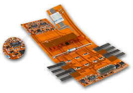
Flexible Printed Circuit Board Assembly
Keeping the electrical components safe during Flexible printed circuit board assembly is a critical part of the design process. A few simple measures can help to ensure safety for the flex circuit and all its connections. The main risk of any flexible PCB is delamination. This can occur anywhere in the flex section of the board or along the interface between the rigid and flex sections. It can lead to a complete failure of the assembly, so strong features must be incorporated into the design to prevent delamination.
To avoid this, a large and consistent bend radius should be used throughout the flex section of the board. The smaller the bend radius, the more stress that will be introduced and the more likely it is to damage the copper. The bend radius should be based on the maximum number of times the flex section will be bent over its life cycle.
In a flexible printed circuit board, signals should never be routed at sharp angles. Sierra Circuits recommends a 90-degree bend radius and a minimum of 40mm for a single-layer flex. The higher the bend radius, the less stress that will be introduced to the copper and the board as a whole.
How to Ensure Safety During Flexible Printed Circuit Board Assembly
It’s also important to consider the material that will be used for the flex circuit. This will determine the maximum number of times that it can be bended and whether it should be considered static or dynamic. A static flex circuit will flex only a few times in its lifetime and is usually assembled straight onto the rigid component. A dynamic flex circuit will need to be able to withstand thousands of bends and must therefore have a stronger and more durable design.
The flex circuit’s thickness, width and spacing is also very important to avoid damage and failure. Copper is known to suffer from work-hardening and fatigue fractures with tight radii and repeated bending, so it’s recommended to stagger traces and pads to avoid weak points. It is also possible to reduce the amount of copper on a flex circuit by using panel plating instead of button plating. This will help to decrease the cost and production time of the flex circuit.
Another issue that can affect the reliability of a flexible circuit is plated through-holes (vias). When they are placed over a stiffener, they are at greater risk of cracking and peeling off during bending. To reduce this, vias should be placed as far away as possible from the flex section of the board and they should have annular rings and tear-drops to help them retain their structure during bending.
To further reduce the chance of damage to the flex circuit, plated corners should always be rounded and not squared or hex-shaped. A hex-shaped corner can crack under compression and is more likely to peel from the flex layers than a tangent curved corner. It is also a good idea to add tabs or anchors to vias in areas that will be subjected to high-bending stresses. This will help to maintain their integrity during the assembly process and protect the underlying traces.